22.09.2026
Design and operating principle of the Flow rocket engine
rocket engine, schematic, principle
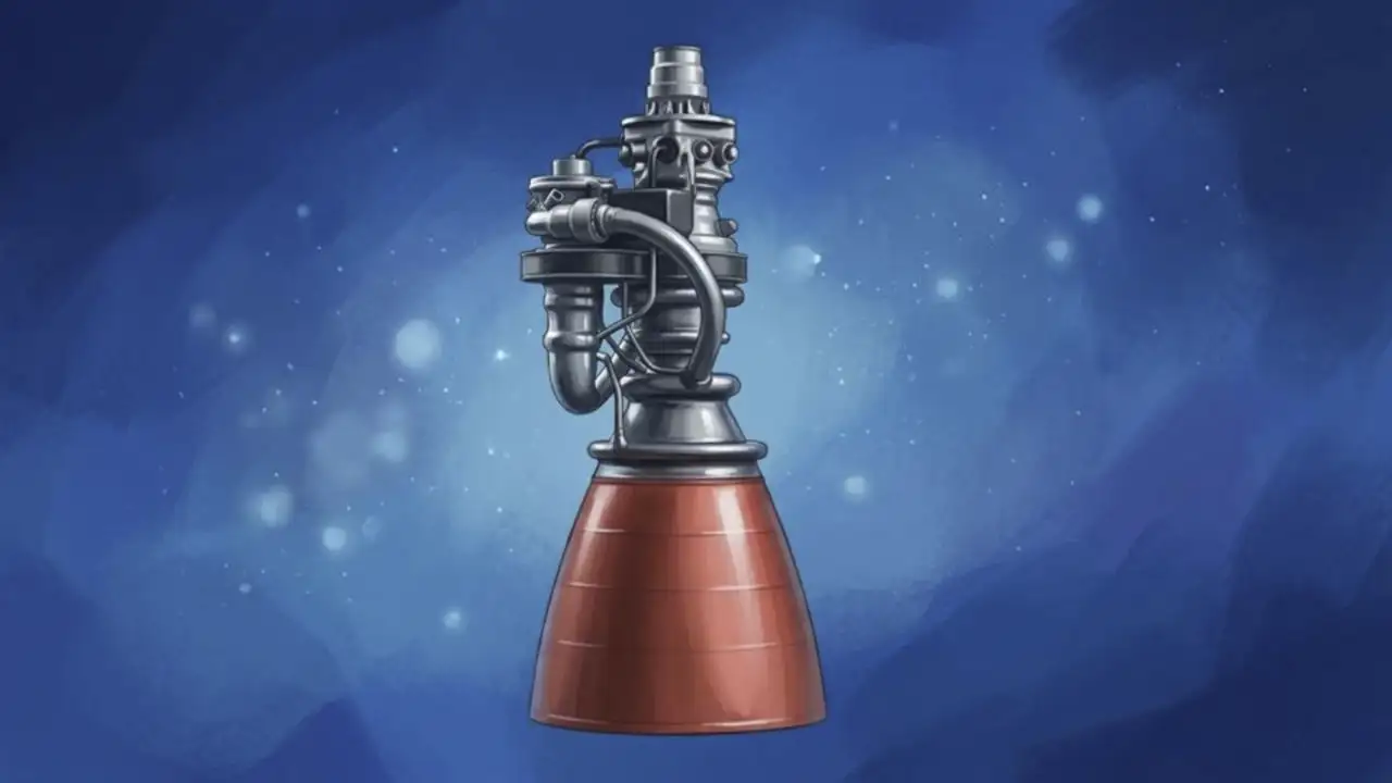
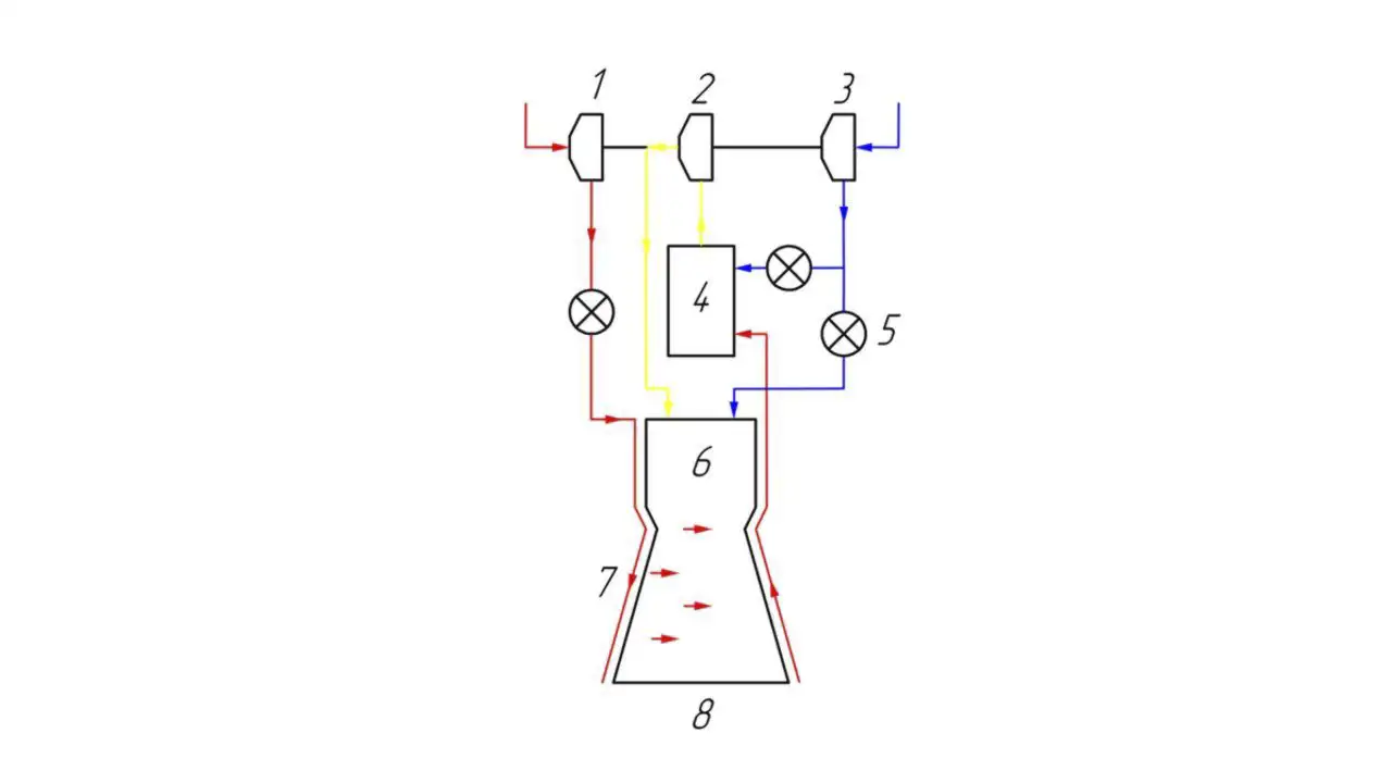
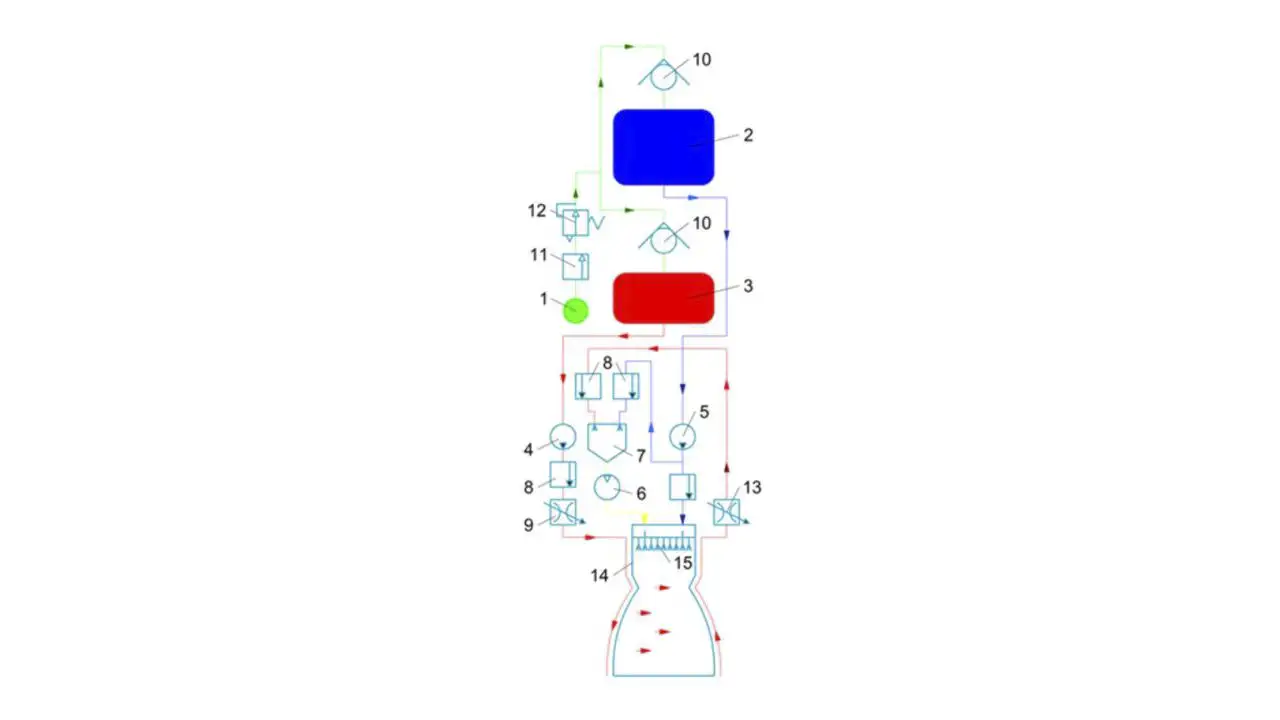
The Flow rocket engine is a closed-cycle liquid-propellant rocket engine featuring full propellant gasification and operating on liquid methane and oxygen. In this full-gasification cycle, the oxidizer turbopump is driven by the bulk of the oxygen flow mixed with a small fraction of methane, while the fuel turbopump is driven by the bulk of the methane flow mixed with a small fraction of oxygen; both streams—oxidizer and fuel—are fully gasified in separate gas generators before entering the combustion chamber (Figure 1).
Characteristics of the Flow rocket engine:
1) Rocket engine type: chemical
2) Propellant state: liquid-propellant rocket engine
3) A bipropellant liquid rocket engine consists of an oxidizer and a fuel.
4) Propellant state: liquid (pressure decreases as the propellant level in the tank drops)
5) Propellant feed method: turbopump assembly. Pump-fed systems supply propellant to the engine using pumps driven by a gas turbine.
6) Combustion cycle/process: In a staged-combustion engine (gas-generator cycle), the gas generated—after passing through the turbopump assembly's turbine—is directed into the combustion chamber, where it undergoes further combustion.
7) Reusable engine
Engine thrust depends on the gas flow velocity: p = mv. The quantity numerically equal to the product of gas mass and its velocity—and sharing the direction of that velocity—is called momentum. A rocket engine expelling gases produced by fuel combustion generates a force directed opposite to the flow; this is called reactive thrust, or simply thrust. Thrust can be measured in standard units of force: kilograms (kg) or newtons (N). Rocket motion is accompanied by a decrease in mass due to the expulsion of gases generated during fuel combustion: v = U · ln(m₀/m). This relationship shows that the greater the rocket's final mass (m), the greater its initial mass (m₀) must be. The higher the gas exhaust velocity (U), the greater the final mass can be for a given initial mass. The higher the gas exhaust velocity (U), the higher the rocket's velocity can be. Thus, achieving high launch vehicle velocity requires a high gas exhaust velocity.
Unlike a solid-propellant rocket engine. A liquid-propellant rocket engine allows for thrust regulation over a wide range and for repeated start-stop cycles, which is particularly important for maneuvering in space and for landing. Due to the combination of these characteristics, the liquid-propellant rocket engine is preferred for use as the main engine of space launch vehicles and as a maneuvering engine.
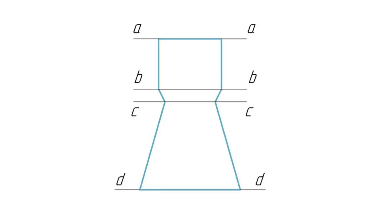
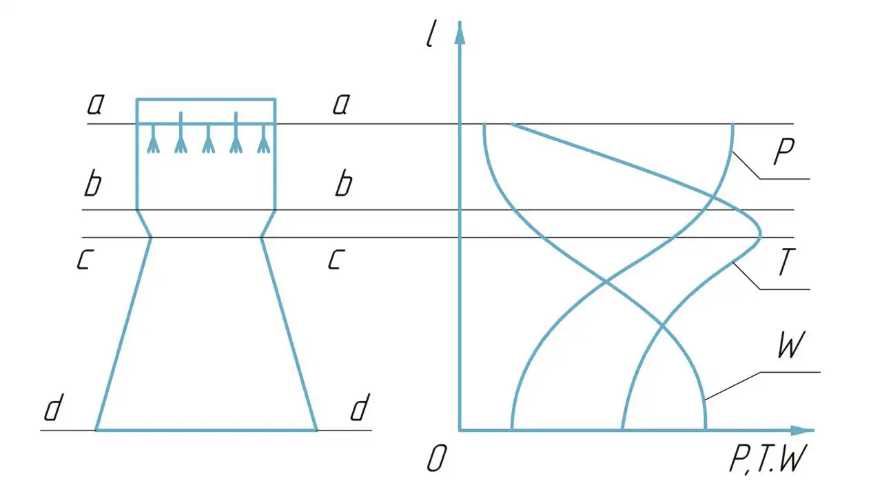
The rocket engine chamber has the following characteristic cross-sections (Figure 2):
a — chamber inlet;
b — combustion chamber outlet / nozzle inlet;
c — geometric minimum;
d — nozzle outlet or nozzle exit plane.
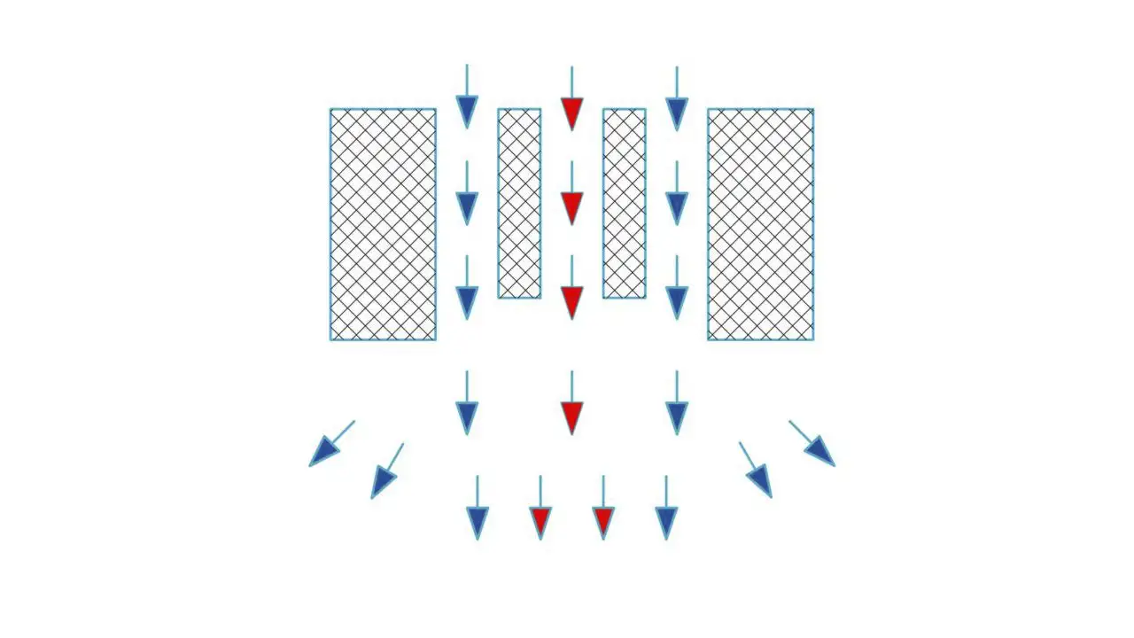
Fuel and oxidizer are fed from their respective tanks to the pumps (Figure 3) under slight overpressure (0.2–0.5 MPa). This tank pressure is generated by a displacement gas supplied from cylinder 1. Within the pumps, the pressure of the propellant components is significantly increased. The bulk of the oxidizer and fuel flows into the combustion chamber of the rocket engine 14. The chamber is the primary assembly of the liquid-propellant rocket engine, as its main function corresponds to that of the engine itself; it generates the primary component of the engine's thrust. The liquid-propellant rocket engine chamber consists of an injector head, a combustion chamber, and a nozzle, which are structurally integrated into a single unit. Oxidizer from the pump is fed via pipelines directly into the injector head and to the injectors 15. Coaxial swirl injectors (Figure 4) are used to feed propellant into the combustion chamber.
The fuel, however, first enters the chamber's cooling passage—the space between the inner combustion wall and the outer structural wall, which are mechanically connected to one another. As it flows through the cooling passage, the fuel cools the chamber walls while simultaneously heating up itself. From the cooling passage, the fuel flows into the injector head and to the injectors. The oxidizer and fuel are then fed into the chamber through their respective single-component injectors. A small portion of the oxidizer and fuel is diverted from the lines downstream of the pumps and fed into the liquid-propellant gas generator 7. The gas generator produces the working fluid for the gas turbine. The generator gas, consisting of the combustion products of the primary propellant, has a relatively low temperature in the range of 600–1100 K; otherwise, the turbine nozzle assemblies and rotor blades would fail or burn out. This reduction in combustion product temperature is achieved by supplying an excess of one of the propellant components to the gas generator. From the gas generator, the combustion products flow into turbine 6, where they perform work. The thermal and potential energy of the working fluid is converted into mechanical energy at the turbine rotor, which drives the oxidizer pump 5 and the fuel pump 4. After passing through the turbine, the gaseous combustion products are exhausted through recovery nozzles, where they expand to generate additional thrust. The bulk of the propellant mass flow enters the combustion chamber via the injector head. The injectors spray the oxidizer and fuel into the combustion chamber, atomizing, mixing, and distributing them throughout the chamber volume. Subsequently, the propellant droplets heat up, vaporize, and mix in the gas phase. The prepared propellant mixture ignites and burns. The chemical energy of the propellant is converted into thermal energy, heating the resulting combustion products to a high temperature. A large volume of high-temperature gaseous combustion products is generated, serving as the working fluid for the liquid-propellant rocket engine (LPRE) chamber. Propellant combustion occurs at a virtually constant static pressure along the length of the combustion chamber's flow path. The pressure within the combustion chamber is approximately 25.0 MPa. As the propellant burns, the temperature of the working fluid increases along the length of the combustion chamber from section (a) to section (b), reaching a maximum at the nozzle inlet (Figure 2). The velocity of the combustion products increases slightly along the length of the combustion chamber because the proportion of fuel converted into combustion products rises, thereby increasing the volume of the working fluid (Figure 5). From the combustion chamber, the working fluid enters the nozzle, where it undergoes geometric acceleration. The thermal and potential energy of the combustion products is converted into the kinetic energy of the gas jet exiting the nozzle. The velocity of the working fluid rises sharply along the nozzle, reaching the speed of sound at the critical section (c) and a supersonic speed in the range of 2500–4000 m/s at the exit section (d). The higher the exhaust velocity of the combustion products, the greater the engine thrust generated per unit of fuel mass flow. As it moves through the nozzle, the working fluid expands, and both its static pressure and static temperature drop along the flow path. The stagnation temperature remains constant, as does the stagnation pressure; the latter decreases only slightly along the length of the combustion chamber due to the presence of thermal resistance.
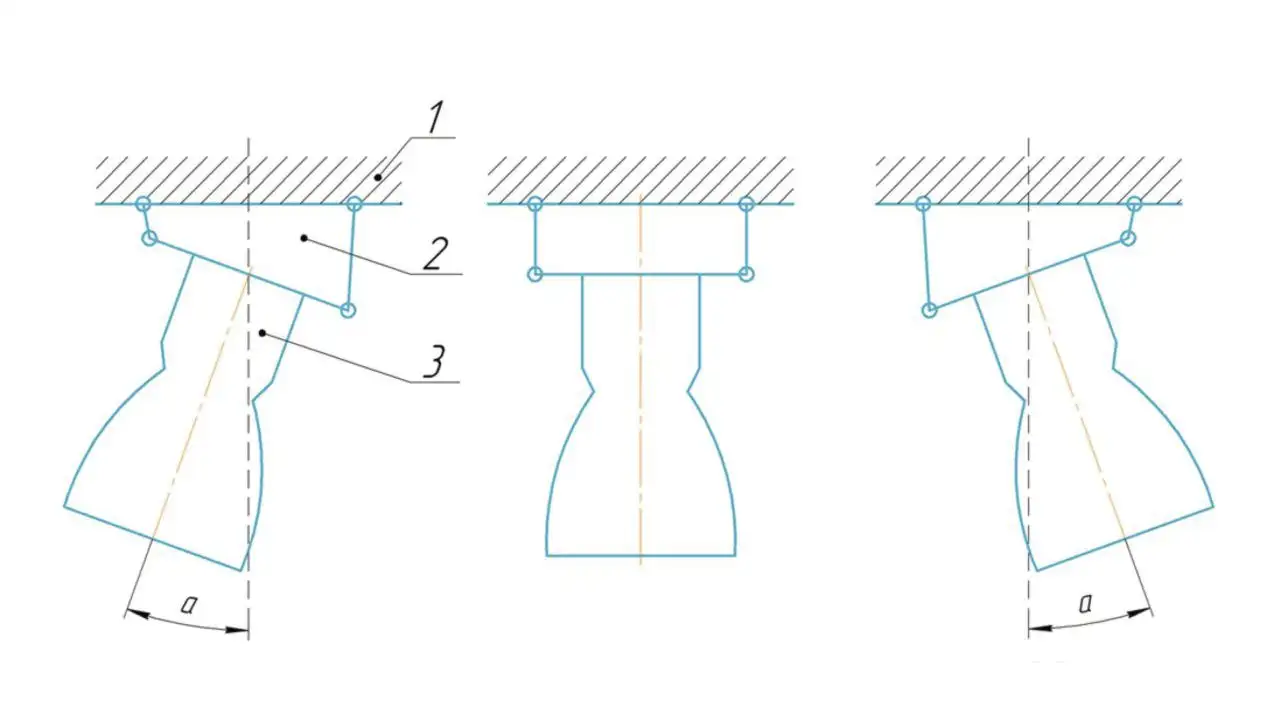
A rocket propulsion system consists of a single rocket engine, a propellant storage and feed system, steering actuators, and auxiliary devices (Figure 6).