21.09.2026
Design and operating principle of the A37 airliner's turbofan engine
engine, turbofan, design, principle
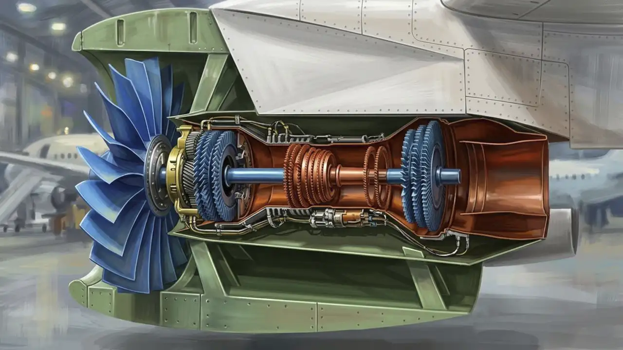
The twin-spool, geared high-bypass turbofan engine of the A37 airliner produces 110 kN of thrust, which is approximately 11 tons of thrust. The engine length is 3.5 m. The dry mass of the engine is 2,800 kg. Located on the low-pressure rotor is a 2-meter diameter fan consisting of 20 wide carbon-fiber blades with titanium nose cones. The fan generates 80% of the engine's total thrust. The bypass ratio of the engine is 12:1. This means that only one-twelfth of the air from the fan enters the core. First, the airflow in the core enters a 3-stage low-pressure compressor located on the low-pressure shaft. A single compressor stage consists of two parts. The rotor blades are moving—they are fixed to the shaft and rotate along with it. The stator vanes are stationary—they are fixed to the engine casing and remain motionless. Passing through the stationary stator guide vanes on the engine casing, the airflow's angle of attack is corrected. Then, the flow enters the rotor blades, which accelerate it. After exiting the rotor, it passes through the stator vanes of the next stage, and so forth. The function of the stator vanes is to convert air velocity into pressure. They straighten the flow so that it correctly enters the subsequent rotor blades. In this way, they increase engine efficiency by reducing turbulence. The rotor blades accelerate the airflow, imparting velocity to it. As the rotor blades spin the air, the flow accelerates and gains high speed, but the pressure is not yet high. The stator vanes decelerate this accelerated flow and convert its kinetic energy into increased pressure. If the air were allowed to proceed further without stator vanes, the next rotor would operate inefficiently. After the low-pressure compressor, the air enters an 8-stage high-pressure compressor located on the high-pressure shaft. The high-pressure compressor compresses the air 50 times, heating it to 300 °C, and the air enters the annular combustion chamber through small fuel nozzle channels. The fuel-air mixture ignites uniformly in the combustion chamber. It is precisely due to this pressure that the fuel burns well in the combustion chamber. The combustion chamber maintains proper flow direction and combustion. Annular-type nozzles are used in the combustion chamber to atomize the fuel. The nozzles are two-phase air-blast injectors equipped with channels for fuel and air supply. The nozzle mixes fuel with air, creating a finely dispersed fuel-air cloud for stable and complete combustion. Thanks to the air, the fuel is broken down into small droplets. The nozzles operate at high temperatures and pressures. High spray uniformity prevents localized overheating of the chamber walls. The smaller the droplets, the faster and more completely the fuel burns. Good atomization helps prevent soot formation, minimizing carbon monoxide and nitrogen oxide emissions. The nozzles operate across a wide range of modes, from engine start to cruise flight. A total of 20 nozzles are installed evenly in a ring around the combustion chamber. They are resistant to surge and flameout. Ignition is performed by igniter plugs. There are 2 plugs in the chamber in case one fails to operate. The igniter plugs in the engine serve to initially ignite the fuel-air mixture in the combustion chamber during engine start or in-flight reignition. The igniter plugs receive a high-voltage electrical pulse from the engine ignition system. This pulse creates a spark between the plug electrodes. The spark ignites the fuel-air mixture, which then sustains combustion through a continuous burning process in the chamber. After the combustion chamber, the gas flow passes through a high-pressure turbine made of a heat-resistant nickel alloy, located on the high-pressure shaft, which drives the high-pressure compressor. After the high-pressure turbine, the gas enters the low-pressure turbine located on the low-pressure shaft, driving the low-pressure compressor and the fan via a planetary gearbox. The gearbox in the engine is used to optimize the operation of both the fan and the turbine. With the gearbox, the fan and turbine operate in their optimal regimes. The turbine is highly efficient at high RPM, whereas the fan operates more efficiently at low RPM. The gear ratio of the reducer is 3:1. The rotational speed of the fan is 3,000 RPM, while the rotational speed of the turbine is 9,000 RPM. The gearbox is engineered for immense torque with minimal energy losses. It allows for a fan diameter of up to 2 meters while maintaining compact engine dimensions. The tip speed of the fan blades is approximately Mach 1. A large fan spinning at slower RPM reduces noise levels by nearly 75% as perceived by humans. The noise level from the fan is 50% lower compared to direct-drive engines. The enlarged fan passes a greater mass of air through the bypass duct, reducing specific fuel consumption and increasing takeoff thrust. As a result of this optimization, fuel consumption is reduced by 20%. Fewer turbine stages are required because the turbine rotates faster and transfers energy more efficiently. At the end of the core, hot gas exits through the core nozzle. At the end of the bypass duct, cold air exits through the fan nozzle. The entire engine is enclosed in a casing made of carbon fiber. The engine uses fuel derived from recycled waste, which performs like aviation kerosene.